TM-9-2320-272-24-3 - Page 634 of 799
4-188. HYDRAULIC
TM 9-2320-272-24-3
THIS TASK COVERS:
a.
Removal
b.
Disassembly
c.
Cleaning, Inspection, and Repair
d. Assembly
e. Installation
INITIAL SETUP:
APPLICABLE MODELS
M936/A1/A2
TOOLS
General mechanic’s tool kit (Appendix E, Item 1)
MATERIALS/PARTS
Two locknuts (Appendix D, Item 291)
Three cap and plug sets (Appendix C, Item 14)
Antiseize tape (Appendix C, Item 72)
Drycleaning solvent (Appendix C, Item 71)
PERSONNEL REQUIRED
Two
REFERENCES (TM)
LO 9-2320-272-12
TM 9-2320-272-10
TM 9-2320-272-24P
EQUIPMENT CONDITION
•
Parking brake set (TM 9-2320-272-10).
• Floodlight assembly removed (TM 9-2320-272-102
• Fuel can bracket removed (para. 4-187).
• Hydraulic oil filter housing removed (para. 4-186).
• Hydraulic oil reservoir drained (para. 4-188).
CAUTION
When disconnecting hydraulic lines and hoses, plug all openings to
prevent dirt from entering and causing damage to parts.
NOTE
Have drainage container ready to catch oil.
1.
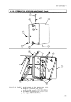
Disconnect hydraulic oil return hose (6) from adapter elbow (7).
2.
Remove two locknuts (1) and screws (2) from two oil reservoir retaining straps (4). Discard
locknuts (1) and separate straps (4) from hydraulic oil reservoir (3).
NOTE
Assistant will help with step 3.
3.
Remove hydraulic oil reservoir (3) from two oil reservoir brackets (5).
NOTE
If a new hydraulic oil reservoir is to be installed, perform step 4.
4.
Remove oil gauge (8), filter screen (9), two pipe plugs (10) and (13), adapter elbow (7), and
drainvalve (11) with pipe plug (12) from oil reservoir (3).
1.
Remove oil gauge (8) and filter screen (9) from top of oil reservoir (3).
2.
Remove adapter elbow (7), drainvalve (11), and pipe plugs (10) and (13) from oil reservoir (3).
3.
Remove pipe plug (12) from drainvalve (11).
4-898
Back to Top


