TM-9-2320-272-24-3 - Page 624 of 799
4-185. REAR
TM 9-2320-272-24-3
THIS TASK COVERS:
a. Removal
b. Installation
INITIAL SETUP:
APPLICABLE MODELS
PERSONNEL REQUIRED
M936/A1/A2
TWO
TOOLS
General mechanic’s tool kit (Appendix E, Item 1)
Torque wrench (Appendix E, Item 144)
MATERIALS/PARTS
REFERENCES (TM)
LO 9-2320-272-12
TM 9-2320-272-10
TM 9-2320-272-24P
Cotter pin (Appendix D, Item 81)
Four locknuts (Appendix D, Item 294)
Six lockwashers (Appendix D, Item 392)
Two O-rings (Appendix D, Item 560)
O-ring (Appendix D, Item 477)
O-ring (Appendix D, Item 456)
Five lockwashers (Appendix D, Item 354)
Adhesive sealant (Appendix C, Item 4)
Antiseize tape (Appendix C, Item 72)
EQUIPMENT CONDITION
•
Parking brake set (TM 9-2320-272-10).
•
Hydraulic oil reservoir drained (para. 4-188).
1.
2.
3.
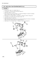
Remove five screws (4), lockwashers (5), washers (6), and cover (3) from floor plate (15). Discard
lockwashers (5).
Remove four screws (2), washers (1), and floor plate (15) from frame (7).
Remove two locknuts (8), screws (11), and washers (10) from front bracket (9) and frame (7). Discard
locknuts (8).
NOTE
4.
5.
Have drainage container ready to catch oil.
Disconnect hose connector (16) from elbow (21).
Remove elbow (21), adapter (20), and valve (19) from elbow (18). Tag adapter (20) and valve (19) for
installation.
6.
Rotate elbow (18) upward on pipe nipple (17) to allow removal of front bracket (9).
7.
Remove three screws (12), lockwashers (13), and front bracket (9) from winch motor (14).
4-888
Back to Top


