TM-9-2320-272-24-3 - Page 638 of 799
4-189. HYDRAULIC
TM 9-2320-272-24-3
THIS TASK COVERS:
a Removal
b. Installation
INITIAL SETUP:
APPLICABLE M0DELS
REFERENCES (TM)
M936/A1/A2
TM 9-2320-272-10
TOOLS
TM 9-2320-272 24P
General mechanic’s tool kit (Appendix E, Item 1)
EQUIPMENT CONDITION
MATERIALS/PARTS
• Parking brake set (TM 9-2320-272-10).
Eight lockwashers (Appendix D, Item 350)
• Hydraulic oil reservoir removed (para. 4-188).
Four locknuts (Appendix D, Item 291)
Adhesive sealant (Appendix C, Item 4)
NOTE
Both hydraulic oil reservoir brackets are replaced the same way.
1.
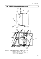
Remove two locknuts (2), screws (9), straps (3) and (4) and insulator strips (5) from reservoir
bracket (1). Discard locknuts (2).
2.
Remove two insulator strips (6) from bracket (1).
3.
Remove four screws (7), lockwashers (8), and bracket (1) from vehicle. Discard lockwashers (8).
1.
Install bracket (1) on vehicle with four new lockwashers (8) and screws (7).
2.
Install two insulator strips (6) on bracket (1).
3.
Install two straps (3) and (4) on bracket (1) with two new locknuts (2) and screws (9).
NOTE
Use adhesive sealant to install old or new insulator strips to
brackets and/or straps.
4.
Install two insulator strips (5) under straps (3) and (4).
4-902
Back to Top


