TM-9-2320-272-24-3 - Page 646 of 799
4-193. BOOM
TM 9-2320-272-24-3
THIS TASK COVERS:
a.
Removal
b.
Installation
INITIAL SETUP:
APPLICABLE MODEL
REFERENCES (TM]
M936/A1/A2
LO 9-2320-272-12
TOOLS
General mechanic’s tool kit (Appendix E, Item 1)
Torque wrench (Appendix E, Item 144)
Lifting device
Chain
TM 9-2320-272-10
TM 9-2320-272-24P
EQUIPMENT CONDITION
• Parking brake set (TM 9-2320-272-10).
• Boom lowered (TM 9-2320-272-10).
• Hydraulic oil reservoir drained (para 4-188).
MATERIALS/PARTS
Cotter pin (Appendix D, Item 59)
Lockwasher (Appendix D, Item 350)
Cap and plug set (Appendix D, Item 14)
PERSONNEL REQUIRED
Two
GENERAL SAFETY INSTRUCTIONS
• All personnel must stand clear during hoisting
operations.
• Elevating cylinder is heavy. Use caution when
removing or installing elevating cylinder.
CAUTION
When disconnecting hydraulic lines and hoses, plug all openings to
prevent dirt from entering and causing internal parts damage.
NOTE
Left and right elevating cylinders are removed and installed in the
same way. Bight elevating cylinder is covered in this procedure.
NOTE
• Have drainage container ready to catch oil.
• Tag lines for installation.
1.
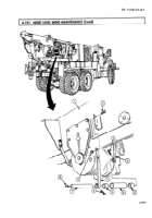
Disconnect cylinder oil supply line (6) and oil return line (5) from cylinder adapter fitting (10) and
snubber valve (9) at bottom of elevating cylinder (11).
WARNING
All personnel must stand clear during hoisting operations. A
snapped cable, or shifting or swinging load, may cause injury to
personnel.
2.
Using chain and lifting device, lift boom (1) until boom (1) weight is fully supported and upper
retaining pin (2) is free.
3.
Remove screw (4), lockwasher (3), and upper retaining pin (2) from elevating cylinder (11) and
boom (1). Discard lockwasher (3).
WARNING
Elevating cylinder is heavy. Remove with the aid of assistant and
a lifting device or injury to personnel may result.
4.
Remove cotter pin (7), lower retaining pin (8), and elevating cylinder (11) from turntable (12).
Discard cotter pin (7).
4-910
Back to Top


