TM-9-2320-272-24-3 - Page 648 of 799
4-194. BOOM
TM 9-2320-272-24-3
THIS TASK COVERS:
a. Removal
b. Installation
INITIAL SETUP:
APPLICABLE MODELS
M936/A1/A2
TOOLS
General mechanic’s tool kit (Appendix E, Item 1)
Torque wrench (Appendix E, Item 145)
Lifting device
Chains
MATERIALS/PARTS
Locknut (Appendix D, Item 285)
Two lockwashers (Appendix D, Item 350)
Cap and plug set (Appendix C, Item 14)
1.
2.
3.
4.
5.
6.
7.
4-912
CAUTION
When disconnecting hydraulic lines and hoses, plug all openings to
prevent dirt from entering and causing internal damage to parts.
NOTE
• Have drainage container ready to catch oil.
• Tag hoses for installation.
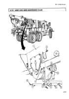
Disconnect cylinder extension hose (5) and retracting hose (4) from two boom adapter elbows (3).
Secure inner boom (1) to outer boom (2) with utility chain to prevent inner boom (1) movement
during hoisting operation.
Attach two utility chains to outer boom (2).
Raise outer boom (2) until weight of boom (2) is fully supported and elevating cylinder retaining
pins (16) are free.
Remove two screws (14), lockwashers (15), and retaining pins (16) from outer boom (2) and two
elevating cylinders (13). Discard lockwashers (15).
WARNING
Before hoisting outer boom away from wrecker, ensure inner boom
is properly secured to outer boom as outlined in step 2 to prevent
injury to personnel.
Remove grease fittings (6) and (12) from pivot pin (7).
Remove locknut (11), pivot pin (7), two sleeve bearings (9), and crane sheave (10) from turntable (8).
Discard locknut (11).
REFERENCES (TM)
LO 9-2320-272-12
TM 9-2320-272-10
TM 9-2320-272-24P
EQUIPMENT CONDITION
• Parking brake set (TM 9-2320-272-10)
• Boom floodlight wire removed (para. 3-385).
• Hydraulic oil reservoir drained (para. 4-188).
• Hoist winch removed (para. 4-192).
GENERAL SAFETY INSTRUCTIONS
• All personnel must stand clear during hoisting
operations.
• Ensure inner boom is secured to outer boom before
hoisting.
WARNING
All personnel must stand clear during hoisting operations. A snapped
cable, or shifting or swinging load, may cause injury to personnel.
Back to Top


