TM-9-2320-273-34 - Page 218 of 801
TM 9-2320-273-34
V
.
Place spring housing assembly (4) in position on the plate with sleeve bushing. Install snapring (2).
w.
Place clamp (3) in position on the cover.
Install two bolts that hold it but do not tighten at
this time.
x.
Place shims (5) and retainer (6) in position on the base.
Install the two screws that hold them.
y.
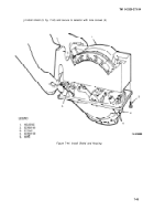
Check the clearance between the retainer (4, fig. 7-39) and plate (4) with a thickness gage ( 1).
The clearance must be 0.002-0.005 in (0.05-0.13 mm). Add or remove shims (3) as required.
Figure 7-39. Check Clearance and Install Shift Guide.
z.
Place guide (2) in position and install the two screws that hold it.
aa.
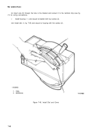
While spring housing assembly
(2,
fig. 740) is kept free of tension (bolts (4) are loose), place the
centerline of the slot in plate (1) in alinement with the, plunger (5).
7-40
Back to Top


