TM-9-2320-273-34 - Page 225 of 801
TM 9-2320-273-34
7-6.
four
Installation.
a.
Mount ratio selector (fig.7-3) on its mounting bracket, aline shift tower brace, and secure with
capscrews and washers. Tighten to 36 ± Ib-ft (49 + 3 N•m).torque.
b.
screws.
c.
CAUTIO N
In step
b,
make sure that holes in gasket
line up with holes in ratio selector.
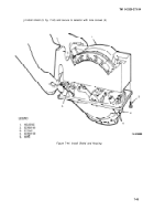
Connect umbilical cord gasket and mounting flange to ratio selector and secure with three cap
Tighten to 36 ± 2 Ib-ft (49 ± 3 N•m) torque.
Connect three wires to terminal strip, as shown in illustration.
Section Ill. TRANSMISSION CASE
7-7. On Vehicle Maintenance.
The following components can be maintained with the transmission installed
on the vehicle.
a.
Pressure Regulator
b.
Quick-Fill Valve
c.
Oil Pump (pressure test only)
d.
Rear Bearing Support Housing, Bearing, and Seals
e.
Rear Clutch
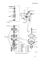
7-8. Pressure Regulator. The pressure regulator (fig. 7-46) changes the air pressure supplied by the vehicle
air system to the correct air pressure needed to engage the output clutch of the transmission.
Figure 7-46. Pressure Regulator
7-47
Back to Top


