TM-9-2320-273-34 - Page 230 of 801
TM 9-2320-273-34
d. Removal and Disassembly.
NOTE
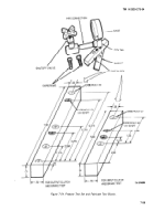
The number of shims, shown in figures
7-48 and 7-49 (6), (9), (13), and (17) will
vary from transmission-to-transmission.
The quantity shown in the figures are
for illustration purposes only,
(1)
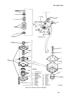
Maintain hand pressure down on the pressure regulator and remove the four mounting
capscrews (1, fig. 7-49) and washers (2).
When removing the pressure regulator in
step (2), shims (6) and (9), guide (7),
spring (8), and piston (10) will remain in
the control group cavity as shown in
illustration. Take care that these parts
do not fall out and become lost.
(2)
Lift off assembled pressure regulator (4),
NOTE
At this point changes can be made to
shims (6) and (9).
(3)
If further disassembly is required remove two screws ( 19) from pressure regulator (4) and
separate the assembly to gain access to shims ( 13) and (17).
e. Assembly and Installation.
NOTE
Be sure the “V” grooves in plates (12,
fig. 7-49), (14), (15), and (18) are
alined during assembly.
(1)
Assemble pressure regulator (4) if disassembled, with thickness of shims as determined in
paragraphs 7-8a and 7-8b, with new O-ring seals. Assemble to center plate ( 15) the following parts: plate
(14), shims (13). upper plate (12), piston (16), shims (17), and lower plate (18). Secure with two screws (19).
(2)
Install O-ring seals on pistons (5) and (11) and install pistons in pressure regulator (4).
(3) Install
O-ring seal on piston (10).
(4) Install shims (9),
piston (10), spring (8), guide (7), and shims (6) in transmission control
cavity.
7-52
CAUTION
Back to Top


