TM-9-2320-273-34 - Page 236 of 801
TM 9-2320-273-34
(6)
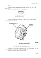
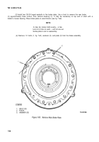
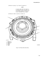
Insert two capscrews into the two jacking screw holes and
with attached O-ring and lip seals.
Leave shims in place (unless damaged)
(7)
Remove O-ring seal.
(8)
Remove lip seal.
force off the support housing
for installation.
(9)
Remove bearing cup and bearing cone if damaged or worn.
b. Installation.
(1)
Cool bearing cup and press into support housing, if removed.
(2) Install lip seal into support housing.
(3)
Install bearing cone.
(4)
Install O-ring seal.
(5)
Install assembled support housing onto the transmission.
(6)
Install four capscrews and washers that fasten the support housing to the transmission case
and tighten to 55 ± 5 Ib-ft (75 ± 7 N•m) torque.
(7)
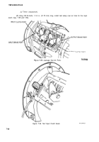
Remove rod and install two capscrews and washers. Tighten 55 ± 5 Ib-ft (75 ± N•m) torque.
(8)
Install speedometer cable, refer to TM 9-2320-273-20.
(9)
Lubricate seal with silicone grease, refer to item 22, appendix B, and install yoke and connect
propeller shaft. (Refer to TM 9-2320-273-20.)
7-12. Transmission Case Removal.
To remove transmission, follow procedures in para 2-1 la.
7-13. Off-Vehicle Repairs.
After the transmission has been removed from the vehicle, the following
maintenance may be performed without disassembling the case.
a.
Front O-ring seal replacement (no detailed procedure is required for this task).
b.
Seal leakage tests for clutches and brakes, para 7-14.
c.
PTO and adapter backlash check, para 21-12 thru 21-15.
7-14. Seal Leakage Tests for Clutches and Brakes.
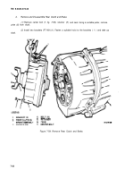
These tests must be performed with the transmission
control removed. (Refer to para 7-17c, steps 1, 2, and 3.)
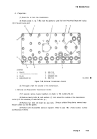
a. Preparation.
The air passage holes in the transmission case to the clutches and brakes do not have
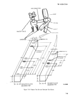
screw threads. It is necessary to make pressure test blocks and gaskets that can be installed on the trans-
mission case to make the test.
(1)
The following items are needed for the tests:
(a)
External air supply with approximately 100 psi (690 kpa).
(b)
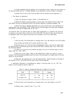
Pressure gage for approximately 125 psi (860 kPa), a 1/4-in. pipe tee, a 1/4-in. pipe –
connection, a 1/4-in. pipe shutoff valve (fig. 7-54).
7-58
Back to Top


