TM-9-2320-273-34 - Page 503 of 801
TM 9-2320-273-34
(2)
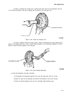
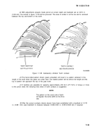
Insert a checking tool (made from a splined axle shaft end) into the differential nest (fig.
11-53). Allow the splines of the tool to engage with the spline of one
side gear only.
Figure 11-53. install the Checking Tool.
(3)
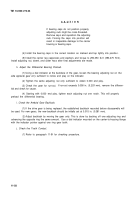
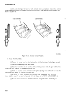
Using a suitable socket and torque wrench, rotate the differential nest while observing the
scale on the torque wrench (fig. 11-54). Correct rolling resistance of the differential assembly is 50 Ib-ft
(68 N·m) torque maximum applied to one side gear;
Figure 11-54 Check Rolling Resistance.
g. Install the Differential and Gear Assembly.
(1)
Pre-lubricate the differential bearings and cups with gear lube (item 30, A
PP
B).
(2)
place the cups over the bearings and position the assembly in the carrier housing,
(3)
Insert the bearing adjusting nuts and turn hand-tight against bearing cups.
11-57
Back to Top

