TM-9-2320-273-34 - Page 502 of 801
TM 9-2320-273-34
(7)
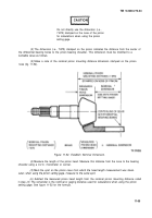
Continue with procedures using the calculated nominal (gaging) distance and the plus or
minus PC variation.
e.
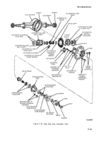
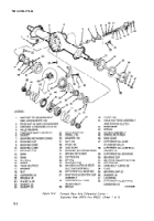
Assemble the Differential and Gear.
The gear should not be pressed or driven
on the case, as this wouId cause excessive
metal particles to lodge between the gear
and case, thus resulting in gear run-out.
Proper installation should, therefore,
incorporate preheating the gear to assure
correct interference fit and to eliminate
metal pickup.
(1) Heat the ring gear in oil to approximately 160°F–180°F (71.1°C-82.2°C) for about
ten minutes before assembly.
(2)
Install twelve bolts, washers, and nuts. Torque to 180-230 Ib-ft (244-31 2 N•m).
(3)
Pre-lubricate the differential case inner walls and all component parts with the recommended
axle lubricant.
(4)
position the thrust washer and side gear in the gear case half.
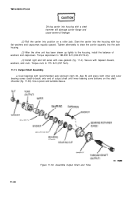
(5) Place the spider with pinions and thrust washers in position.
(6) InstalI the second side gear and thrust washer.
(7)
Position the other case half over the assembly, alining match marks of both halves. Draw
the assembly together with three equalIy spaced capscrews.
(8)
Install the remaining capscrews and torque to 85-115 Ib-ft (11 5-156 N•m).
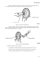
(9) If new bearings are to be used, press squarely and firmly on the differential case halves with
a suitable sleeve.
f. Rolling Resistance of Differential Nest.
(1) Place the differential and ring gear assembly in a vise with soft metal jaws.
11-56
CAUTION
Back to Top

