TM-9-2320-273-34 - Page 505 of 801
TM 9-2320-273-34
(2)
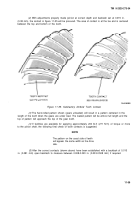
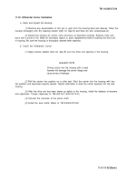
With adjustments properly made (pinion at correct depth and backlash set at 0.015 in.
(0.38 mm), the contact in figure 11-55 will be procured. The area of contact is at the toe and is centered
between the top and bottom of the tooth.
Figure 11-55. Satisfactory Amboid Tooth Contact.
(3)
The hand-rolled pattern shown (gears unloaded) will result in a pattern centered in the
length of the tooth when the gears are under load. The loaded pattern will be almost full length and the
top of pattern will approach the top of the gear tooth.
(4)
If facilities are available for applying approximately 200 Ib-ft (271 N·m) of torque or more
to the pinion shaft, the following final check of tooth contacts is suggested.
NOTE
The pattern on the coast side of teeth
will appear the same width as the drive
side.
(5)
After the correct contacts (shown above) have been established with a backlash of 0.015
in. (0.381 mm) open backlash to measure between 0.008-0.020 in. (0.203-0.508 mm) if required.
11-59
Back to Top

