TM-9-2320-273-34 - Page 517 of 801
TM 9-2320-273-34
b. Remove Interaxle Differential and Cage Assembly.
NOTE
Before disassembly is started, record gear
backlash. Gear must be reset to this figure
at reassembly.
(1)
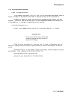
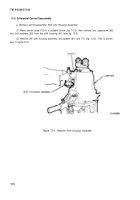
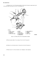
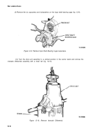
Remove six bolts and six lock washers (fig. 12-6) holding the oil pump adaptor housing
to the carrier case. Remove oil pump adaptor housing and gasket.
(2)
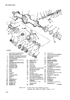
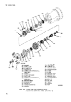
Refer to figure 12-2. Remove two oil hoses(112 and 118), elbows (113, 117, 119 and 124),
reducers (114, 115, 116, 120, 121 and 123) and the screen (122). Tag parts for easy reassembly.
Figure 12-6. Remove Pinion Bearing Cover.
(3)
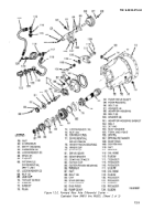
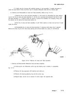
Scratch or paint a line from the adaptor housing (98) to the pump housing (95) and from
the pump housing to the cap (89) for easy alinement during reassembly.
(4)
Remove four bolts (96) and four washers (97) attaching the pump housing (95) to the
adaptor housing (98). Tap the pump housing with small mallet to free it from the adaptor housing.
(5)
Remove six bolts (88) attaching cap (89) to the pump housing (95). Remove the cap and
the cap gasket (91 ). Note position of small hole in gasket relative to lubrication slot in cap. Also note
position of star spring (90) in cap and position of end piece (92). Do not rotate end piece until you have
noted its original position.
(6)
Remove end piece (92), pump gear (93) and pump driver shaft
(94).
12-9
Back to Top

