TM-9-2320-273-34 - Page 526 of 801
TM 9-2320-273-34
(8)
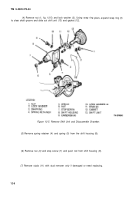
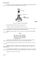
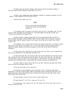
Remove the inner pinion bearing (78) by using a suitable puller that bears against bearing
inner race; or press off with a fixture that supports inner race (fig. 12-17).
Figure 12-17. Remove Inner Pinion Bearing.
e.
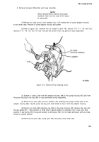
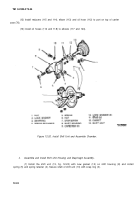
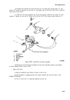
Disassemble Interaxle Differential Assembly (See figure 12-2).
(1)
Remove side gear (132) and bearing cone (134) from carrier.
(2)
If bearings require replacement, remove bearing cup (135) from carrier, using a suitable
puller. Remove the bearing cone from side gear using a press and bearing puller.
(3)
Remove the spider retainer (131) from input shaft (139) and slide interaxle differential
nest from shaft.
NOTE
Before splitting interaxle differential
case halves, make certain identification
marks are clear for correct reassembly.
If markings are not clear, use a punch
or chisel and re-mark.
(4)
Disassemble interaxle case halves (129, 133) by removing eight capscrews (127) and
washers (128). This will free the spider (130), four pinions (136), and thrust washer (137).
(5)
Slide off drive gear (126), washers (125 and 138), and clutch collar (142), from input
shaft (139).
(6)
Remove yoke (151), or flange nut (153), and washer (152), from input shaft (139).
Using a suitable puller, remove yoke or flange. This will free the bearing cage (147); lift cage off from
input shaft (139).
(7)
if bearings require replacement, remove the bearing cones (145 and/or 141), from input
shaft (139), and the bearing cup (146 and/or 140), from bearing cage (147), and remove oil seal (150).
(8)
Remove O-ring (143) and shims (144).
12-18
Back to Top

