TM-9-2320-273-34 - Page 533 of 801
TM 9-2320-273-34
(8)
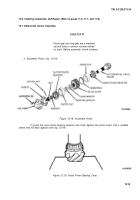
Adding shims will increase endplay, while removing shims will decrease endplay. If
shim pack requires further adjustment, repeat steps
(3)
thru
(6).
(9)
After correct endplay has been established, asemble the remaining capscrew and lock-
washers. Torque capscrews to 40-55 Ib-ft (54-74 N·m).
j.
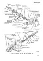
Install Oil Pump (Refer to fig. 2-2).
NOTE
Be sure to aline parts using the painted or
scratched lines made” during disassembly
(see 12-5 b).
(1)
Thoroughly clean the surfaces of the carrier case (76) and of the adaptor (98). Dry both
surfaces, install new adaptor housing gasket (101), and install adaptor housing (98) to carrier case
(76) with six bolts (99) and six washers (100).
(2)
Clean surfaces of adaptor housing (98) and of the pump housing (95). Dry both sur-
faces thoroughly and apply a l/8-inch diameter bead of silicone sealant (item 24, App B) to the pump
housing surface. Apply the sealant material to one surface only and around all fastener holes. (Refer
to para 11-8b).
(3)
Immediately, line up scratch lines and fasten the pump housing (95) to the adaptor housing
(98) with four bolts (96) and four washers (97). If a new pump housing is being installed, position it
against the adaptor housing so that the port stamped is to your right (to the truck’s left when all
assembled).
(4)
Insert pump driver shaft (94) into pump housing (95), and rotate it until its flattened end
slips into the notched end of the differential drive pinion (77).
(5)
Install pump gear (93) onto end piece (92) and insert the assembly into the pump housing
(95), meshing the teeth of the pump gear with the teeth of the pump driver shaft (94), and rotating the
end piece (92) to the proper position, The proper position is with the shaft of the pump gear (the shaft
pressed into the end piece) at the 7 o’clock position as you face the pump on an assembled axle.
(6)
Clean surfaces of pump housing (95) and of cap (89). Install new cap gasket (91) alining
small inner hole with lubrication groove in cap.
(7)
put star spring (90) into cap, legs down.
(8)
Carefully put cap (89) against pump housing (95), lining
UP
scratches made during
disassembly. If new cap is being installed, make sure lubrication groove is alined with small hole in cap
gasket (90) which is alined with lubrication hole on delivery side Of pump housing (95). Fasten cap to
pump housing with six bolts (88).
(9)
Install reducers (116 and 123) to ports of pump housing (95).
(10)
Install elbows(117 and 124) to reducers (116 and 123).
(11)
Install screen (122), reducers (121 and 120), elbow (119), and oil hose (118) to port at
bottom of carrier case (76).
12-23
Back to Top

