TM-9-2320-273-34 - Page 535 of 801
TM 9-2320-273-34
(2)
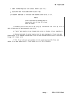
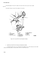
Proceed with inserting the shaft until shift unit (13) mates with housing studs (11) and
gasket (12). Install lock washers (2) and nuts (1); then tighten nuts to 40-55 Ib-ft (54-74 N·m). Install the
stop screw (7) and nut (6).
(3)
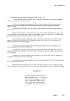
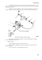
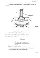
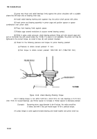
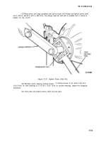
Install fork and yoke assembly (fig. 12-21) into housing. Install bolt (5), spring (4), seat
washer (3), spacer (2), and nut (6). Tighten nut 20-30 Ib-ft (27-41 N·m) torque. Install cotter pin (1).
Figure 12-21. Install Fork and Yoke Assembly.
(4)
Position the shift and housing assembly into the carrier assembly against a new gasket
or silicone sealant (Refer to para 11-8b.)
l. Adjust Shift Shaft.
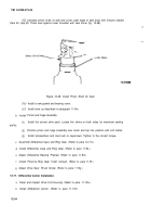
(1) Back
off adjusting screw locknut so screw is free to turn.
(2)
Shift assembly to engaged position with power chamber. Be sure shift collar is fully
engaged with rear gear.
(3)
Turn in screw until it is finger-tight against the push rod.
12-25
Back to Top

