TM-9-2320-273-34 - Page 531 of 801
TM 9-2320-273-34
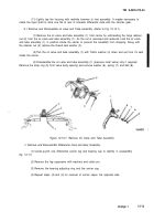
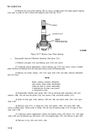
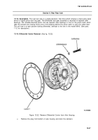
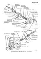
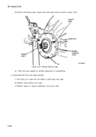
h. Assemble Interaxle Differential Assembly (Refer to Fig. 12-2).
(1)
Press the input shaft rear bearing cup (135) into bore in the carrier. Use a press and sleeve
of the correct diameter to press in the cup.
(2)
Press the input shaft bearing cone (145) onto the new input shaft (139). Use a sleeve to
press on cone by the inner race only. Coat the bearing rollers with the recommended axle lubricant
(item 30, App B).
(3)
Install the clutch collar (142) onto the input shaft splines with the clutch teeth facing the
rear of shaft.
(4)
Prelubricate both sides of the helical drive gear washers (125 and 138) and the gear journal
of the input shaft (139) with gear lube. Place the thrust washer (125) into its pilot bore in the heIical drive
gear and install the drive gear (126) and washer onto the input shaft.
(5)
Assemble the interaxle differential spider (130), pinions (136), and thrust washers (137)
between the case halves (129 and 133). Thoroughly prelubricate both sides of the thrust washers and
spider legs as the parts are being assembled.
(6)
Secure tie assembly together with eight hardened washers (128) and capscrews (127).
Torque capscrews to 60-75 Ib-ft (81-102 N·m).
(7)
Prelubricate the forward side gear teeth (integral with helical drive gear) and install the
interaxle differential nest assembly into the input shaft (139) with the capscrew heads facing toward the
rear of the shaft.
(8)
Retain the interaxle differential nest assembly on the input shaft (139) by installing the
new spider retainer (131) into the groove shaft.
(9)
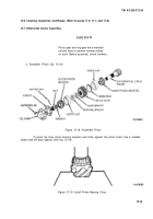
press the input shaft rear bearing cone (134) onto rear side gear (132). Use a sleeve to press
on cone by the inner race only.
(10)
Prelubricate the bearing rollers and side gear teeth. position the carrier upright and place
the rear side gear (132) with bearing cone (134) into carrier against bearing cup (135) previously installed.
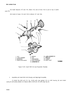
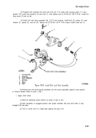
In step
(11),
observe that one helical
gear is marked with an *’X” at one tooth,
while the other helical gear is marked
with a corresponding symbol at one
tooth. These marks must be alined
at installation for correct gear contact.
Change 1
12-21
CAUTIO N
Back to Top

