TM-9-2320-273-34 - Page 524 of 801
TM 9-2320-273-34
(8)
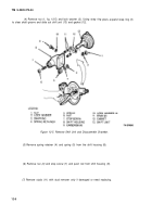
Remove twelve bolts (48 and 53, fig. 12-2); then separate case halves. It may be
necessary to tap sides with a mallet.
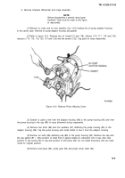
(9)
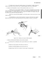
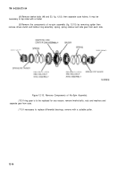
Remove the components of no-spin assembly (fig. 12-15) by removing spider then
remove driven clutch and holdout ring assembly, spring, spring retainer and side gear from each side.
Figure
12-15.
Remove Components of No-Spin Assembly.
(10)
If ring gear is to be replaced for any reason, remove twelve bolts, nuts and washers and
separate gear from case.
(11)
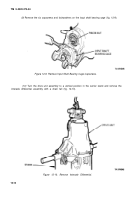
If necessary to replace differential bearings, remove with a suitable puller.
12-16
Back to Top

