TM-9-2320-273-34 - Page 528 of 801
TM 9-2320-273-34
(2)
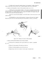
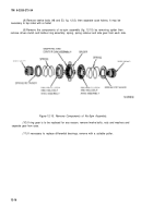
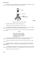
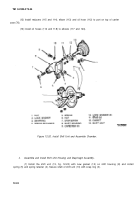
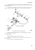
Install shim pack (80) info carrier case (76). (See figure 12-2.)
(3)
Install the inner
CUP
(79) against the shim pack (80).
(4)
Install drive gear (81).
(5)
install the outer cup (84) to bottom in cup bore.
(6)
Lubricate bearing and cups with light machine oil or lubriplate (item 16, App B).
(7)
place the carrier and cap under a press, carrier legs down. Hold drive gear (81) in
position and thread drive pinion (77) up through inner cup (79) and gear (81). Support pinion and
carrier under pinion head. Install “fixed” (thick) cone spacers (82 and 83).
(8)
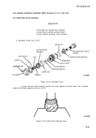
Start outer pinion bearing (85) on drive pinion (77). Press bearing on with a suitable
sleeve that will bear against the cone race. Press bearing in place with two tons of pressure to seat rollers.
(9)
Assemble the pinion nut washer (86) and nut (87) with 100 Ib-ft (136 N·m) torque. Hold
pinion by placing a hardwood block between pinion teeth and carrier wall.
b.
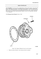
Assemble Differential Case and Ring Gear (see figure 12-2).
CAUTIO N
The ring gear shouId not be pressed or
driven onto the case, as this would cause
excessive metal particles to lodge be-
tween the gear and the case, thus result-
ing in gear runout. Proper installation
shouId, therefore, incorporate preheating
the gear to assure correct interference
fit and to eliminate metal pickup.
(1)
Heat the ring gear (42, fig. 12-2) in oil to approximately 160°F – 180°F for about ten
minutes before assembly.
(2)
If the ring gear has been separated from the case, fasten gear (42) to case (47) with
high-shear strength bolts, Iockwashers, and nuts. Torque to 180-230 Ib-ft (244-312 N·m).
(3)
Assemble and install no-spin assembly as described in paragraph 11-9b.
(4)
If the differential bearings (36 and 49) have been removed, press one onto each end of
assembly using a suitable sleeve.
c.
Install Differential Case and Ring Gear. (Refer
to para 11-9c.)
d. Adjust Differential Bearing Preload. (Refer
to para 11-9d.)
e. Check Gear Back/ash. (Refer
to para 11-9e.) Since this axle is equipped with no-spin assembly,
the clearance should be set as closely as possible to the minimum specified dimension, after satisfactory
tooth contact is obtained (step
f,
following).
12-20
Back to Top

