TM-9-2320-273-34 - Page 521 of 801
TM 9-2320-273-34
(11)
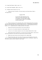
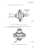
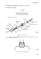
Lightly tap the housing with rawhide hammer to free assembly. It maybe necessary to
rotate the input shaft to aline one flat at rear of interaxle differential case with the transfer gear.
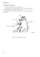
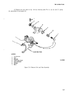
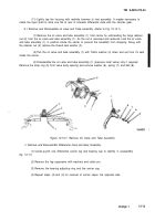
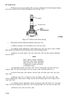
b.1 Remove and Disassemble oil valve and Tube assembly. (Refer to Fig. 12-10.1).
(1)
Remove the oil valve and tube assembly (1) from carrier by unthreading the large retainer
nut (2) from the oil valve and tube assembly (1). As the nut is loosened and removed, hold the oil valve
and tube assembly (1) in position inside the carrier to prevent the assembly from dropping. Along with
the retainer nut (2) remove the thread seal washer (3).
(2)
Pull the oil valve and tube assembly (1) with Teflon washer (4) down and out from it’s seat
inside the carrier.
(3)
Disassemble the oil valve and tube assembly (1) (pressure relief valve) only if required.
Remove the snap ring (5) from valve body opening and remove washer (6), spring (7), and ball (8).
Figure 12-10.7. Remove Oil Valve and Tube Assembly
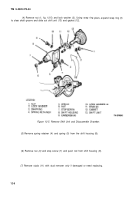
c. Remove and Disassemble Differential Case and Gear Assembly.
(1)
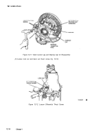
Center-punch one differential carrier leg and bearing cap to identify in reassembly
(fig. 12-11).
(2)
Remove the leg capscrews with washers and cotter pin.
(3)
Remove the bearing adjusting ring and the carrier cap.
(4)
Repeat steps
(2)
and
(3)
for removal of carrier capon the opposite side.
Change 1
12-13
Back to Top

