TM-9-2320-273-34 - Page 529 of 801
TM 9-2320-273-34
f.
g.
Check Pinion-to-Ring Gear Tooth Contact.
(Refer to para 11-9f.)
Adjust Drive Gear Thrust Screw.
(Refer to para 11-9g.)
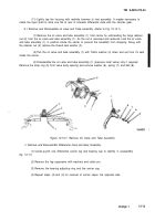
g.1 Assemble and Install Oil Valve and Tube Assembly.
(Refer to Fig. 12-10.1).
NOTE
If the oil valve and tube assembly was not
disassembled, start with step
(2)
for instal-
lation into carrier.
(1)
Install the pressure relief valve ball (8), spring (7), small diameter first, washer (6), in the oil
valve and tube assembly, and secure with snap ring (5).
(2)
Position Teflon washer (4) over threaded body portion of oil valve and tube assembly (1).
(3)
Working from inside the carrier housing, insert the valve locating pin of the oil valve and
tube assembly (1) into threaded capscrew hole at front of carrier and the threaded portion of valve body
through hole in top of carrier.
(4)
Hold the oil valve and
washer (3) and large retainer nut (2).
tube assembly (1) in this position and install the thread seal
Torque retainer nut (2) to 50 Ib-ft (68 N·m).
Change 1
12-20.1/12-20.2 (Blank
Back to Top

