TM-9-2320-273-34 - Page 574 of 801
TM9-2320-273-34
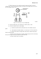
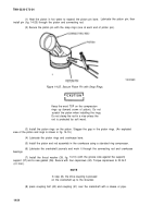
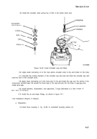
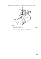
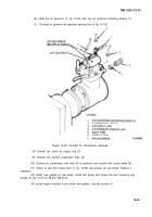
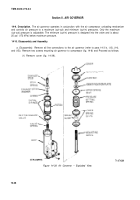
(9) Install the unloader valve spring (fig. 14-29) in the intake valve seat.
Figure 14-29. install Unloader Cap and Body.
(10) Apply clean lubricating oil to the new yellow unloader body O-ring and install on the body.
(11) Lubricate the outside diameter of the unloader cap and seal and slide the unloader cap with
seal into bore of the unloader body.
(12) Apply clean lubricating oil to the body and O-ring and install the cap over the spring in the
compressor cylinder head. Be certain the three legs of the cap protrude into the three of
intake valve seat.
(13) Install washers, Iockwashers, and capscrews. Torque alternately to a final
8-11 lb-ft (11-15 N-m).
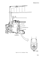
(14) Install the air and water fittings, as shown in figure 14-1.
14-8. Installation (Engine in Chassis).
a. Preparation.
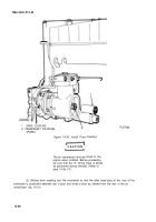
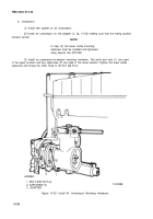
(1)
Install drive coupling (1, fig. 14-30) to crankshaft coupling splines (2).
openings of the
torque of
14-27
Back to Top

