TM-9-2320-273-34 - Page 580 of 801
TM9-2320-273-34
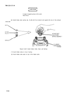
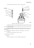
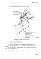
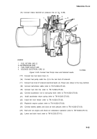
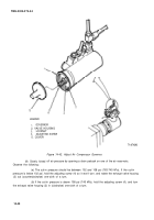
(6) Install the air governor (7, fig. 14-35) with two air governor mounting screws (1).
(7)
Connect air governor air pressure sensing line (4, fig. 14-35).
Figure 14-35. Connect Air Compressor Hookups.
(8)
Connect fan clutch air supply line (3).
(9) Connect two alcohol evaporator lines (2).
(10) Connect air compressor inlet tube (5) to governor and secure with screw clamp (6).
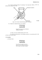
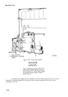
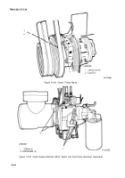
(11) Check to see that timing mark (1, fig. 14-36) and pointer (2) are alined. Realine if
necessary.
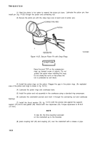
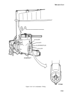
(12) Install new gasket on fuel pump, install fuel pump and torque the four mounting cap-
screws (2, fig. 14-37) to 49 Ib-ft (66 N-m).
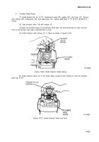
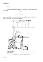
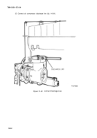
(13) Install engine retarder micro switch and gasket. Use two screws (1).
14-33
Back to Top

