TM-9-2320-273-34 - Page 584 of 801
TM9-2320-273-34
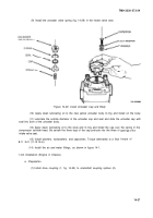
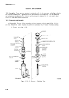
(2) Using a pair of retainer ring pliers, remove the retaining ring.
(3) Remove the locknut, identification plate and then the hex-shaped upper spring seat from
the adjusting screw.
(4) Remove the pressure setting spring, one lower spring seat, spring guide and the other
lower spring seat from the adjusting screw.
(5) Remove the exhaust stem and stem spring from the piston.
(6) Invert the body and tap it on a wood surface and remove the piston.
(7) Remove the inlet and exhaust valve and valve spring.
(8) Remove the two outer piston O-rings.
(9) With a hooked wire, remove the exhaust stem O-ring and the exhaust stem washer from
the stem bore of the piston.
(10) Remove and clean strainers.
b. Inspection.
Clean all metal parts in mineral spirits. Wipe rubber parts dry and inspect for wear
or damage. Inspect body for cracks or other damage. Be particularly careful that all air passages in the
body, strainers, exhaust stem, and piston are not obstructed. Repairs to governor parts are not recom-
mended. Replace all parts which are worn or damaged.
c. Assembly.
NOTE
Prior to assembly all parts must be
lubricated with Bendix lubricant, Part
Number 240176, or equivalent.
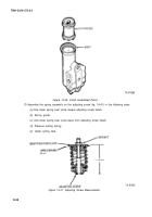
(1)
Install the exhaust stem O-ring in its groove in the stem bore of the piston and the ex-
haust stem washer.
(2) Install the two outer O-rings on the piston.
(3) Install the inlet and exhaust valve in the bottom of the piston.
(4) Install the valve spring with its narrow coil end against the valve. Press the spring down
until the large coil end snaps into the groove inside the piston.
(5) Position the exhaust stem spring over the exhaust stem with the narrow coil end toward
the stem head. Carefully press the stem into the stem bore of the piston.
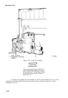
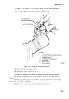
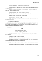
(6) Install the assembled piston in the body (fig. 14-40). Push the piston in until it bottoms.
14-37
Back to Top

