TM-9-2320-273-34 - Page 665 of 801
TM 9-2320-273-34
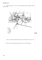
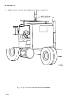
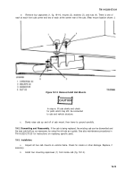
Using a hoist and sling arrangement, as shown in figure 19-13, lower the cab on the four mounts
(2, fig. 19-14); then secure with capscrews (1), washers (3) and nuts
(4).
d.
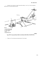
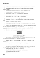
Install heater tube clamps (1 and 2, fig. 19-12) on heater tubes and secure to firewall with
sheetmetal capscrews.
e.
f.
9-
h.
i.
j.
k.
screws.
/.
m.
screws.
n.
install clamp (3) on electrical cable and secure to firewall with sheetmetal screw.
Install electrical plug (5) and secure to bracket with nut (4).
Connect electrical plug (fig. 19-11 ) to receptacle on right side of firewall.
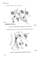
Connect compressed air lines ( 1 and 2, fig. 19-10) to firewall connectors.
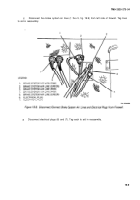
Connect electrical plugs (6 and 7, fig. 19-9) to firewall connectors.
Connect brake system air lines ( 1 thru 5, fig. 19-9) to firewall connectors.
Install clamps (1, 2, and 3, fig. 19-8) and secure to lower left side of firewall with sheetmetal
Install plug (5) and secure to bracket with nut (4).
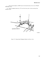
Install receptacle bracket (fig. 19-7) and secure to left rear corner of cab with three sheetmetal
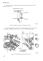
Lower the circuit breaker panel; then connect yellow air line (1, fig. 19-6) to top of INTERAXLE
DIFFERENTIAL control and red air line (2) to PARK BRAKE valve.
o.
Lower the panel adjacent to WIPER control; then connect blue air line (3) to TRAILER
EMERGENCY valve.
P.
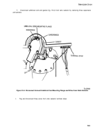
Connect three wires to ratio selector terminal board (fig. 19-4).
In step
9,
make sure that holes in gasket
line up with holes in ratio selector.
q.
Connect umbilical cord gasket and mounting flange (fig. 19-4) to ratio selector and secure with
three capscrews and washers. Tighten to 36 ± 2Ib-ft (49 ± 3 N•m) torque.
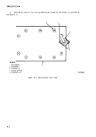
Install floor plate (4, fig. 19-3) with ten screws (5).
lnstalI grommet (2) and retainer (1) with
two screws (3).
s.
Connect engine retarder floor switch by installing two wires as tagged (fig. 19-2).
t.
Install headlight dimmer switch (fig. 19-2) and secure to floor with two screws.
.
On model M915, install spare tire support assembly (fig. 19-1) and secure to vehicle frame with
four capscrews, eight washers, and four nuts. Tighten nuts to 50 lb-ft (68 N•m) torque.
Install spare tire (M915 only – refer to TM 9-2320-273-10).
v.
w.
Using TM 9-2320-273-20 for instructions, perform the following tasks.
(1) If removed, install tailpipe and muffler.
(2) Install lower steering column.
19-14
c .
CAUTION
r .
Back to Top

