TM-9-2320-273-34 - Page 672 of 801
TM 9-2320-273-34
(8)
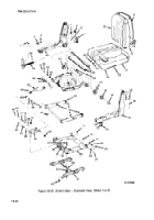
Remove yoke (7) and bearing (61 ).
(9)
Remove torsion bars (65).
(10)
Remove rollers (38) and (43) from shock lever (39).
(11)
Drive out two roll pins (66) and remove shaft (67).
(12)
Remove two snap rings (40), washers (42), and hinge shaft (41) that retains the lower
end of the shock absorber (50) and remove the shock absorber. Remove four bearings (49) from shock
absorber.
(13)
Remove snap rings (40) and hinge shaft (41 ) and remove shock lever (39).
(14)
If necessary, two bumpers (63) and (64) may be removed from the underside of pan
(12).
(15)
Remove two snap rings (48), roller and bearing assemblies (47), washers (46), and pins
(45) from outer lower assembly (69).
(16)
Remove four lubrication fittings (24).
(17)
Remove four nuts (25), Iockwashers (26), studs (28), and snap rings (27).
(18)
Separate outer lever (69) from center lever (62).
(19)
If necessary, remove lubrication fitting (44).
(20)
Remove four bearings (70).
(21)
If necessary, remove bumpers (71) and (72).
(22)
Separate center lever (62) from base (29).
(23)
Remove two lubrication fittings (51 ).
(24) Remove two nuts (52), Iockwashers (53), washers (54), studs (55), roller and bearing
(56), and snap rings (57).
(25)
Remove four capscrews (32), eight washers (33), four Iockwashers (34), and four
nuts (37).
(26)
Separate base (29) from slide rails (31 ).
(27)
Latch wire (30) may be removed from slide rails (31), if necessary.
(28)
Remove two bearings (35) and (36) from base (29).
d.
Inspection.
Inspect all bearings and rollers for defects. Inspect shock absorber for wear and
signs of leakage. Replace all components found defective.
19-21
Back to Top

