TM-9-2320-273-34 - Page 675 of 801
TM 9-2320-273-34
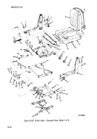
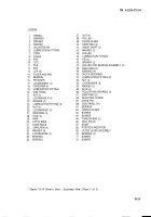
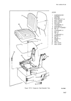
19-10. Driver’s Seat Assembly.
a.
Frame and Related Components.
(1) Press two bearings (35) and (36) into base (29).
(2)
If removed, install latch wire (30) between slide rails (31).
(3)
Position base (29) on slide rails (31).
(4)
Install four capscrews (32), eight washers (33), four Iockwashers (34), and four nuts
(37) to secure base (29) to slide rails (31). Tighten nuts securely.
(5) install two snap rings (57) on studs (55).
(6)
Install
(7)
Install
(52).
(8)
Install
two roller bearings (56) and washers (54) over studs (55).
stud (55) in center lever (62) and secure with two Iockwashers (53) and nuts
two lubrication fittings (51 ).
(9)
If removed, install two bumpers (71) and (72) in base (29).
(10)
Position center lever (62) to base (29).
(11)
Install four bearings (70).
(12)
If removed, install lubrication fitting (44).
(13)
Position outer lever (69) to center lever (62) and secure with four studs (28), snap
rings (27), Iockwashers (26), and nuts (25).
(14)
Install four lubrication fittings (24).
(15)
Install two pins (45), washers (46), roller and bearing assemblies (47) and snap rings
(48) to outer lever assembly (69).
(16)
If removed, install two bumpers (63) and (64) to the underside of pan (12).
(17)
position shock lever (39) into position on base (29) and secure with one hinge shaft
(41 ) and two snap rings (40).
(18)
install four bearings (49) in shock absorber (50).
(19)
position shock absorber (50) in shock lever (39) and secure with one hinge shaft (41),
two washers (42) and two snap rings (40).
(20)
Position shock absorber (50) in center lever (62) and secure with shaft (67). Stake
shaft (67) with two roll pins (66).
19-24
Back to Top

