TM-9-2320-273-34 - Page 761 of 801
TM9-2320-273-34
23-2. Removal.
Removal and replacement procedures for all major Winterization Kit components,
except for the engine oil heating unit, are contained in TM 9-2320-273-20.
23-3. New Installation of Circuit Breaker Box and Power Receptacle.
a.
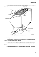
Remove four existing bolts (1, fig. 23-1 ) and nuts (4) from the right hand cab support (2).
b.
Install two mounting angles (3) to cab support with four bolts (1) and nuts (4); torque to
90-120 Ib-ft (122-162 N-m).
c.
Attach mounting plate (9) to mounting angles (3) with four bolts (12), washers (13), and nuts
(14)
d.
install circuit breaker box (8) with receptacle (5) attached to plate (9) with three bolts (7),
washers (6), lockwashers (1 O) and nuts (11).
23-4. New Installation of Transmission Oil Heater.
a.
Drain transmission oil (Refer to TM 9-2320-273-20).
b.
Remove 1-1 /4-inch pipe plug from tapped hole (9, fig. 23-2) on forward left hand side of
transmission.
Screw heater element (3) with heater element mounting plate (4) attached, into tapped hole
(9). c
“
d.
Install wire assembly (6) through heater cover (5); attach wires to heater element mounting
plate (4) as shown.
Secure heater cover (5) to heater element mounting plate (4) with two capscrews (2) and lock-
washers (1).
—
f.
Remove existing bolt (8) from left hand front face of transmission, route wire assembly (6)
as shown to circuit breaker box on right hand side (see fig. 23-1), insert bolt (8) thru clamp (7) but do
not tighten as wire assembly from engine oil heater will also be routed through this same clamp.
9.
Refill transmission (Refer to TM 9-2320-273-20).
23-5. New Installation of Engine Oil Heater.
a.
Drain engine oil (Refer to TM 9-2320-273-20).
b.
Remove engine oil pan (Refer to TM 9-281 5-222-34& P).
c.
Drill a 1.265 inch diameter hole (1, fig. 23-3) thru left hand side of oil pan (3) as shown in
view A.
d.
Drill and tap two .38-16 inch diameter 29 holes (2) .840-.870 inch deep in left hand outside
of oil pan (3) as shown in view A.
Drill two .172 inch diameter holes for screws (4) .360 inch deep in bottom inside of oil pan as
show: in view A; these must be in line with four screen mounting bolts (5).
f.
Remove four screws (5) and oil screen (7). See view B.
9.
Position heating element (11 ) in bottom of oil pan (3) as shown in view B.
23-6
Back to Top


