TM-9-2320-273-34 - Page 755 of 801
TM9-2320-273-34
NOTE
In step e, fan shaft setscrew (fig. 22-6) is
accessible from top, through blades of fan.
e.
Install fan on motor shaft (either end). Shaft should protrude approximately l/4-inch beyond
end of fan. Tighten l/8-inch allen-head setscrew tosecure fan to shaft.
f.
Repeat step e for other fan at opposite end of motor shaft.
In step g, when installing motor and fan
support plate, do not rub against the
heater core.
9.
Position motor and fan support plate (fig. 22-5) into heater housing and secure with four
capscrews.
h.
Place control shutter into opening at end of housing (fig. 22-4). It may be necessary to rotate
the shutter to a position where it will fit into its retaining hole.
i.
Install the other control shutter by rotating it to its full upright position (as shown); then slide
it into retaining holes.
j.
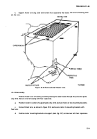
Pull wires through hole in housing (fig. 22-3) and install grommet.
k.
Mount cover on housing and secure with nine capscrews (fig. 22-2).
22-5. Installation.
(Refer to TM 9-2320-273-20.)
22-10
. .
.—
CAUTION
Back to Top


