TM-9-2320-273-34 - Page 92 of 801
TM9-2320-273-34
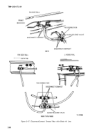
(9) Remove seven capscrews, nuts, and washers that fasten the brake backing plate and remove
the backing plate with attached brake assemblies (fig. 2-45).
Figure 2-45, Remove/Install Backing Plate.
c. Installation procedure.
(1)
Make sure that vehicle is supported as shown in figure 2-41.
(2) Mount backing plate with attached brake assemblies onto the
figure 2-45. Push seven capscrews through backing plate and secure assembly
Tighten to 170 Ib-ft (231 N-m) torque.
NOTE
Three men may be required to position
and install assembled axle on vehicle.
front axle, as shown in
with washers and nuts.
(3) Using a sling and hoist, place axle on a jack and roll jack into position under vehicle.
(4) With one man guiding each end of axle, raise the axle until it is against each leaf spring.
Make sure that spring center bolt enters the guide hole.
2-76
Back to Top


