TM-9-2320-279-20-1 - Page 356 of 985
TM 9-2320-279-20-1
STE/lCE
Instructions (Cent)
2-16.
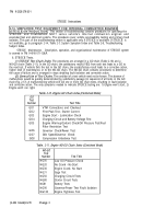
SIMPLIFIED TEST EQUIPMENT FOR INTERNAL COMBUSTION ENGINES (STE/lCE)
@
INTRODUCTION (CONT).
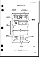
(2)
TEST SELECT SWITCHES.
The TEST SELECT switches are used to select the actual test to be
~erformed. There are ten ~ositions on each switch numbered O through 9. The number dialed into these
●
.
switches is read by the ‘; ’TM when you press the TEST button. Chang;ng the TEST SELECT switch position
has no effect until the TEST button is pushed.
(3)
TEST B~lTTO”
Depressing and releasing the TEST button causes the test measurement to begin.
The measured value will appear on the readout display. The reading will be in units normally used for the
particular vehicle measurement. These units are listed on the flip cards. The TEST BU’lX)N must be
pressed and immediately released. Depressing and holding the TEST BUTlON down initiates an offset test
as described in k.(3).
(4)
READOUT DISPJQW
The READOUT DISPLAY will show different types of readouts during
testing up to a maximum of 4 characters (for example .8.8.8.8). The types of readouts are described in
detail later in this paragraph but are summarized as follows:
(a) Status Readout.
This type of readout keeps the operator informed of what is happening such as
power applied, failed test, etc.
(b)
Numerical Readout.
This type of readout is the measured value in units of the measurement
being made. For example, if measuring O-45 volts DC, the number 24 on the display indicates 24-volts.
(c)
Error Readout.
This type of readout indicates that, for example, the wrong test number was
selected, the transducer is not connected, or the VTM is faulty.
(5)
FLIP CARDS.
The flip cards list the 2-digit test number system for selecting the various tests.
The cards also summarize the test operating instructions contained in this chapter.
(6)
POWER/DCA CONNECTOR J1.
Connector J1 connects the VTM to either a vehicle diagnostic
connector using the DCA cable, or to the vehicle batteries using the power cable. Operating power and
signals from the transducers are supplied to the VTM through the DCA cable.
(7)
TRANSDUCER CABLE CONNECTORS J2 and J3.
Connector J2 or J3 connects the VTM to any
transducer in the transducer kit. Operating power is supplied to the transducer and signals from the
transducer are supplied to the VTM through the cable. Connectors J2 and J3 are identical and can be
interchanged with each other or used in combination.
(8)
TEST PROBE CABLE CONNECTOR J-4.
Connector J4 connects test leads to the VTM when doing
manual voltage and resistance tests.
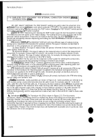
g. Cc#b/e Assemblies.
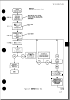
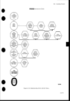
Cable assemblies are shown in Figure 2-21. Cable assemblies are referred to by
cable number and by a name which describes how the cable is used. For example, cable W 1 is the DCA
cable, cable W2 is the Test Probe cable, etc. If necessary, the two transducer cables (W4) can be joined with
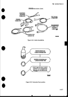
the adapter supplied in the transducer kit to make one long cable. When cables are connected, the large
key on the cable connector mates with a keyway on the transducer connector or the VTM connector for
proper installation. Figure 2-22 shows how the key and keyway should be lined up. If there is any
difficulty during testing, and it is suspected that a cable is bad, refer to TM 9-4910-571-12&P to check cable
continuity.
h.
Transducer
Kit (TK).
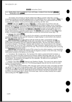
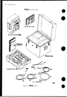
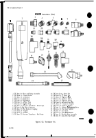
The Transducer Kit (TK) is shown in Figure 2-23. The kit contains
transducers, adapters, and fittings stored in a molded tray. Many of the fittings do not have part number
markings. However, the number shown with each item will help to identify the item easily. Before
installing any Transducer Kit items on the vehicle, be sure to clean the mounting surfaces. This is
particularly important if opening fuel lines or tapping into manifolds. Dirt particles entering the engine can
cause damage to both the engine and the transducer kit items. The transducers are precise devices housed
in rugged bodies. However, they should be kept clean and handled with reasonable care. In particular, keep
the connectors free of dirt and grease.
2-276
Back to Top

