TM-9-2320-279-34-1 - Page 320 of 709
TM 9-2320-279-34- 1
Electrical System Maintenance Instructions (Cont)
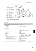
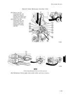
(50)
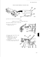
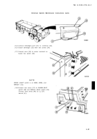
Install two heater
compartment covers (115)
on console (2) with
11 screws (116).
(51)
Install heater compartment
cover (117) with eight
screws (118).
(1)
(2)
(3)
(4)
(5)
(6)
(7)
c. Follow-on Maintenance .
Install ETHER START
switch (TM 9-2320-279-20).
Install starter switch
(TM 9-2320-279-20).
Install TRACTION
CONTROL switch
(TM 9-2320-279-20).
Install ENGINE STOP switch
[TM 9-2320-279-20).
Install TRACTION
CONTROL indicator light (TM 9-2320-279-20).
Install instrument panel (TM 9-2320-279-20).
Connect batteries (TM 9-2320-279-20).
END OF TASK
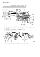
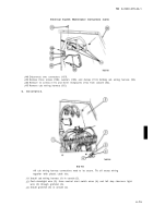
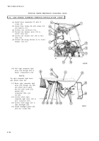
6-14. ENGINE WIRING HARNESS REMOVAL/INSTALLATION .
This task covers:
a. Removal
c. Follow-on Maintenance
b. Installation
INITIAL SETUP
Models
Personnel Required
Al l
MOS 63W, Wheel vehicle repairer
Test Equipment
References
None
Non e
Special Tools
Equipment Condition
None
TM or Para
Condition Description
Supplies
TM 9-2320-279-20 Batteries disconnected.
Connector, electrical, butt, Rem 31,
Appendix C
Special Environmental Conditions
Tags, identification, Item 60, Appendix C
Non e
Tape, insulation, electrical, Item 62,
General Safety Instructions
Appendix C
Non e
Ties, cable, plastic, Item 65, Appendix C
Level of Maintenance
Direct Support
6-8 7
Back to Top

