TM-9-2320-280-20-2 - Page 408 of 951
TM 9-2320-280-20-2
4-170
Change 3
4-93. REAR DOOR BLACKOUT SWITCH/BRACKET MAINTENANCE
Manual References
TM 9-2320-280-10
TM 9-2320-280-24P
Equipment Condition
• Battery ground cable disconnected
(para. 4-73).
• Rear doors lowered (TM 9-2320-280-10).
1.
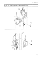
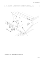
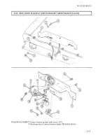
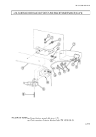
Remove two locknuts (6), washers (2), capscrews (3), and washers (2) from bracket (1) and bracket (7).
Discard locknuts (6).
2.
Disconnect two leads (4) from leads (5). Remove bracket (1).
3.
Remove two screws (18), lockwashers (17), and leads (14) and (16) from switch (15). Discard
lockwashers (17).
4.
Remove two nuts (13), washers (12), screws (9), switch (15), switch lever (11), and spacer plate (10)
from bracket (1).
a. Removal
b. Installation
This task covers:
a. Removal
b. Installation
NOTE
Prior to removal, tag leads for installation.
NOTE
Perform step 5 only if wiring harness is damaged.
NOTE
Perform step 1, only if wiring harness was removed.
5.
Remove assembled locknut (20) screw (8), clamp (19) and wiring harness (21) from bracket (1).
Discard assembled locknut (20).
1.
Install clamp (19) and wiring harness (21) on bracket (1) with screw (8) and assembled
locknut (20).
2.
Install spacer plate (10), switch lever (11), and switch (15) on bracket (1) with two screws (9),
washers (12), and nuts (13).
3.
Install leads (14) and (16) on switch (15) with two lockwashers (17) and screws (18).
4.
Connect two leads (4) to leads (5).
5.
Install bracket (1) on brackets (7) with two washers (2), capscrews (3), washers (2), and
locknuts (6).
INITIAL SETUP:
Applicable Models
M996, M996A1, M997, M997A1, M997A2
Tools
General mechanic’s tool kit:
automotive (Appendix B, Item 1)
Materials/Parts
Assembled locknut (Appendix G, Item 131)
Two lockwashers (Appendix G, Item 169)
Two locknuts (Appendix G, Item 76)
Back to Top


