TM-9-2320-280-20-2 - Page 422 of 951
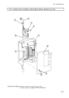
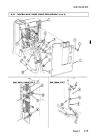
4-97. CONTROL BOX ASSEMBLY REPLACEMENT (M996, M996A1) (Cont'd)
TM 9-2320-280-20-2
4-184
Change 3
7.
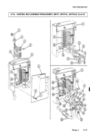
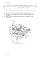
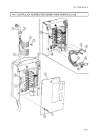
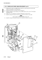
Remove locknut (12), lockwasher (13), washer (11), NBC harness lead (10), and power cable (9)
from positive stud (2). Discard lockwasher (13) and locknut (12).
8.
Remove two screws (6) and two NBC harness leads (7) from mounting buss (8).
9.
Remove plain-assembled nut (15), clamp (14), and NBC harness leads (7) and (10) from control box
stud (17). Discard plain-assembled nut (15).
10.
Remove nut (18) and negative cable (20) from mounting buss capscrew (3).
11.
Remove power cable (9) from power stud (2) and clamp (16) from control box stud (17).
12.
Remove three screws (5), lockwashers (4), and control box (1) from body (21).
Discard lockwashers (4).
1.
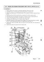
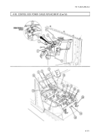
Install control box (1) on body (21) with three lockwashers (4) and screws (5).
2.
Install negative cable (20) on mounting buss capscrew (3) with nut (18).
3.
Install power cable (9) and NBC harness lead (10) on power stud (2) with washer (11),
lockwasher (13), and locknut (12).
4.
Install two NBC harness leads (7) on mounting buss (8) with two screws (6).
5.
Install clamp (16) power cable (9), negative cable (20), clamp (14), and NBC harness leads (7)
and (10), on control box stud (17) with plain-assembled nut (15).
b. Installation
Back to Top

