TM-9-2320-280-20-2 - Page 658 of 951
TM 9-2320-280-20-2
6-26
Change 3
6-11. GEARED HUB REPLACEMENT
This task covers:
a. Removal
b. Installation
INITIAL SETUP:
Tools
General mechanic’s tool kit:
automotive (Appendix B, Item 1)
Puller kit (Appendix B, Item 167)
Materials/Parts
Three cotter pins (Appendix G, Item 14)
Lockwasher (Appendix G, Item 146)
Four locknuts (Appendix G, Item 79)
(Basic/A1 Series)
Four locknuts (Appendix G, Item 128)
(Basic/A1 Series)
Four locknuts (Appendix G, Item 104)
(A2 Series)
Four locknuts (Appendix G, Item 105)
(A2 Series)
Sealing compound (Appendix C, Item 45)
Sealer (Appendix C, Item 39)
Personnel Required
One mechanic
One assistant
Manual References
TM 9-2320-280-10
TM 9-2320-280-24P
Equipment Condition
• Wheel removed (para. 8-3).
• Steering stop removed (para. 6-19).
• Air lifting bracket removed, rear only
(para. 6-20).
General Safety Instructions
Geared hub must be supported during
removal and installation.
CAUTION
Use of a pickle fork in lieu of the puller kit may damage
serviceable components (boots).
NOTE
• Have drainage container ready to catch drained fluid.
• Removal and installation procedures are basically the same for
front and rear geared hubs. This procedure covers the front geared
hub.
1.
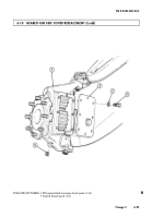
Remove drainplug (29) from geared hub (9) and drain geared hub (9).
2.
Install drainplug (29) in geared hub (9).
3.
Remove capscrew (22), washer (23), vent line bracket and clamp (24) from geared hub (9).
4.
Loosen clamp (10) and disconnect vent line (1) from geared hub fitting (11).
5.
Remove cotter pin (25), slotted nut (26), and washer (27) from tie rod end (28) and geared hub (9).
Discard cotter pin (25).
6.
Using puller, disconnect tie rod end (28) from geared hub (9).
7.
Remove access plug (14), washer (15), axle halfshaft retaining capscrew (13), lockwasher (12) and
disconnect halfshaft (20) from geared hub (9). Discard lockwasher (12).
WARNING
Geared hub must be supported during removal and installation.
Failure to support geared hub may cause injury to personnel or
damage to equipment.
NOTE
Note direction of outer capscrew for installation.
8.
Remove four locknuts (21), washers (16), capscrews (17), and washers (16) from lower ball joint (18)
and lower control arm (19). Discard locknuts (21).
a. Removal
Back to Top


