TM-9-2320-280-20-2 - Page 666 of 951
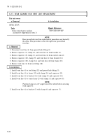
a. Removal
1.
Remove drainplug (2) from geared hub (1) and drain geared hub (1). Install drainplug (2) in geared
hub (1). Tighten drainplug (2) to 8-13 lb-ft (11-18 N
•
m).
2.
Remove four capscrews (5), washers (4), and steering arm cover (3) from geared hub (1).
4.
Using retaining nut wrench, remove retaining nut (14 ), key washer (13), and keyed washer (12)
from spindle (7). Discard key washer (13).
NOTE
Have drainage container ready to catch oil.
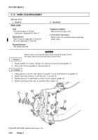
6-13. GEARED HUB SPINDLE SEAL REPLACEMENT
This task covers:
a. Removal
b. Installation
Manual References
TM 9-2320-280-10
TM 9-2320-280-24P
Equipment Condition
Wheel removed (para. 8-3).
General Safety Instructions
Ensure locktab on key washer is bent completely
into slot on retaining nut.
INITIAL SETUP
Tools
General mechanic’s tool kit:
automotive (Appendix B, Item 1)
Special Tools
Wrench (Appendix B, Item 127)
Installer (Appendix B, Item 128)
Driver handle (Appendix B, Item 75)
Materials/Parts
Key washer (Appendix G, Item 65)
Plain encased seal (Appendix G, Item 291)
Grease (Appendix C, Item 22)
Sealer (Appendix C, Item 39)
Lubricating oil (Appendix C, Item 29)
Sealing compound (Appendix C, Item 45)
TM 9-2320-280-20-2
6-34
Change 3
NOTE
For new configuration, two locktabs on key washer must be bent
away from retaining nut for removal.
NOTE
If four-slotted retaining nut TN-07 is present, it is recommended to
replace it with eight-slotted retaining nut 12342680.
3.
Bend locktab on key washer (13) away from retaining nut (14).
Back to Top

