TM-9-2320-280-34 - Page 289 of 1258
TM 9-2320-280-34
6-3.
60 AMPERE ALTERNATOR REPAIR
This task covers:
a.
Removal
d.
Assembly
b.
Cleaning
e.
Bench Testing
c.
Inspection
INITIAL SETUP:
Tools
Materials/Parts (Cont'd)
General mechanic's tool kit:
Grease (Appendix B, Item 20)
automotive (Appendix G, Item 1)
Insulating compound (Appendix B, Item 26)
Lubricating oil (Appendix B, Item 33)
Test Equipment
Silicone compound (Appendix B, Item 56)
Multimeter (Appendix G, Item 120)
Seal sleeve tool (Appendix C, Fig.
6)
Special Tools
Manual References
Torx socket (Appendix G, Item 28)
TM 9-214
TM 9-2320-280-20
Materials/Parts
TM 9-2320-280-24P
Locknut and woodruff key kit
(Appendix E, Item 67)
Personnel Required
Slip ring end kit (Appendix E, Item 202)
One mechanic
Drive end kit (Appendix E, Item 12)
One assistant
Fifteen lockwashers (Appendix E, Item 83)
Two screw and lockwasher assemblies
Equipment Condition
(Appendix E, Item 147)
•
Alternator removed (TM 9-2320-280-20).
Strap (Appendix E, Item 206)
•
Alternator pulley removed (TM 9-2320-280-20).
Adhesive sealant (Appendix B, Item 2)
Maintenance Level
Direct support
a.
Disassembly
NOTE
Prior to removal, tag leads for installation.
1.
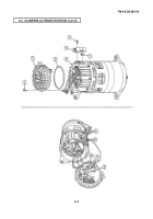
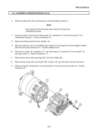
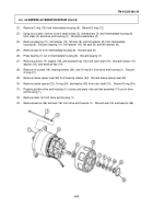
Remove access plug (7) from end housing (4).
2.
Remove six screws (1), end cover (2), and O-ring (3) from end housing (4).
Disconnect four leads (10)
from four terminals (11) on regulator (12).
Discard O-ring (3).
NOTE
Regulator is part of end cover.
Do not disassemble.
3.
Remove two screw and lockwasher assemblies (6) and output plate cover (5) from end housing (4).
Discard screw and lockwasher assemblies (6).
4.
Remove sealer from three stator leads (8).
5.
Unsolder and disconnect three stator leads (8) from three stator lead terminals (9).
6-2
Back to Top

