TM-9-2320-283-20-1 - Page 456 of 926
TM 9-2320-283-20-1
STE/ICE TROUBLESHOOTING.
2-15.
STE/ICE VTM SET-UP PROCEDURE TEST NUMBER GO1.
The STE/ICE VTM set-up and internal checks must be done before performing any truck tests.
Do test number
G01 to checkout the proper function of the VTM and associated cables.
2-16.
STE/ICE DESCRIPTION AND OPERATION.
a.
General.
The following
describes the
operation of the Simplified Test Equipment/Internal
Combustion
Engines
(STE/ICE) system and contains detailed operating procedures.
STE/ICE is used to test the serviceability of M915A1 trucks and to perform primary fault detection and isolation.
After the
MOS has identified a faulty part or subsystem, he/she is referred to a paragraph number for replacement or
repair procedures for individual parts.
b.
Description and Operation.
STE/ICE is a testing system that performs tests and
measurements on
internal
combustion engines.
STE/ICE measures
standard voltage, current, resistance, pressure, temperature, and speed
(RPM).
Special tests, such as compression unbalance test and starter system evaluations, are performed by STE/ICE.
Standard equipment
functions including
vacuum pressure gage, compression gage, low-current tester, and multimeter
are features of the STE/ICE set.
STE/ICE is portable and operates on either 12 or 24-volt truck batteries or equivalent power source.
The
STE/ICE system consists of a Vehicle
Test Meter (VTM), a Transducer Kit (TK), four electrical cables, a transit case, and
technical publications.
c.
Personnel Required.
One mechanic is
required to perform most tests.
An additional mechanic is required
to perform certain specific tests.
d.
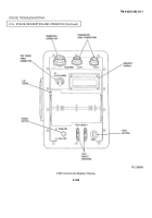
Vehicle Test Meter.
(1)
General.
The VTM provides a method for the MOS to test M915A1 truck electrical
and mechanical
components.
Readings are
either pass/fail indications or digital displays in units familar to the mechanic (psi, rpm, volts,
ohms, amps, etc.).
The Diagnostic Connector
Assembly
(DCA) is mounted
on a bracket attached to the left hand
(driver’s side).
of the engine block, and provides accessability to the
most frequently needed test points.
The use of
the
VTM through the DCA is
referred to as DCA mode.
The VTM interfaces with the vehicle directly with transducers
installed on the vehicle in the DCA mode. The
use of
the
VTM through
the TK
is
referred to
as TK
mode.
The
VTM
interfaces with the vehicle with transducers from the transducer kit (TK).
The DCA
and the TK can be
used at the same
time.
This may be necessary when the diagnostic connector assembly has a missing transducer, such as when doing the
oil pressure test.
If a transducer is missing, a no
sensor indication (E002) is displayed
when a measurement is made.
If
this happens, the TK mode can be
2-331
Back to Top


