TM-9-2320-283-20-1 - Page 470 of 926
TM 9-2320-283-20-1
STE/ICE TROUBLESHOOTING.
2-19.
VEHICLE TESTING TROUBLESHOOTING PROCEDURES.
a.
General.
To troubleshoot an M915A1 truck problem, the mechanic can use the STE/ICE (vehicle test meter
and transducers) and the truck test cards found in the back of this TM.
b.
Data Entry Tests.
For information regarding Data Entry, Cylinder Entry,
Vehicle ID Entry, and Data Display
Tests, refer to TM 9-4910-571-12&P.
c.
Offset Tests.
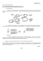
The STE/ICE VTM performs a test by setting the TEST SELECT switches to the test number
and pressing the TEST button.
For some tests, an offset is required before the test itself can be performed.
This is done
by selecting the number of the desired test and holding the TEST button down for several seconds.
The offset test nulls out characteristic differences in the VTM, test leads, and transducers.
It zeros the meter.
Once the offset
is performed, the VTM automatically corrects for the
offset before displaying measured values.
The
displayed offset value should be checked against limits on the vehicle test card
sheet.
If
the
displayed value
is outside
these
limits, either
the transducer or the test cable is
faulty and must be replaced.
This is another form of self-test.
The offset is performed when each transducer is connected. All tests requiring offset are identified by a (*) on the flip cards
and by OFFSET LIMITS on
the vehicle
test card sheet.
The offset
test is performed with the test probe cable or
transducer connected to the VTM.
Care should be taken to see that no stimulus
is applied to the transducer.
Test probe
cable leads should
be shorted together.
To perform
an offset test, dial the
test number into the TEST SELECT
switches.
Press and hold the TEST button until the prompting message
CAL appears on the display.
In a few seconds
after release of the TEST
button, a number will appear.
This is
the measured offset value associated with the test probe
cable or transducer and cable.
d.
Control Tests.
These tests are used to change (or control) the way a vehicle test is displayed or
the way
it is
run.
There are
four (4) control tests:
01
Interleave (alternates back and forth to
display RPM with next test).
02
Display minimum value for next test.
03
Display maximum value for next test.
04
Display peak-to-peak value for next test.
Control tests 01, 02, 03, and 04 specify the action to be taken by the next test only.
A subsequent test will reset
the control.
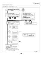
(1) Interleave (Test 01).
This test alternately measures engine speed and a second
parameter such as
fuel
pressure
or alternator
voltage.
To initiate interleave, dial 01 into the TEST SELECT switches and press and release the
TEST button.
The prompting
message PASS will signal the
mechanic to dial in the second test number and again press
and release the TEST button.
2-345
Back to Top


