TM-9-2320-283-34-2 - Page 518 of 570
TM 9-2320-283-34-2
CAB AND BODY.
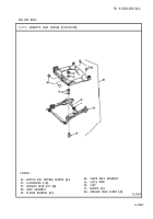
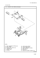
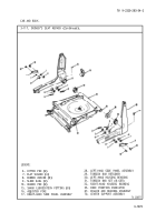
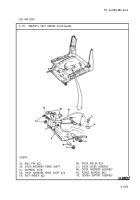
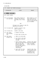
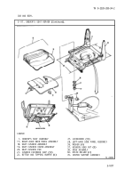
3-117. DRIVER'S SEAT REPAIR (Continued).
LOCATION/ITEM
ACTION
REMARKS
SHOCK ABSORBER ASSEMBLY
NOTE
If any shock absorber flange bearing
was removed; do step 99, otherwise go
to step 100.
99. Four bearings
(69).
Install in item (68) if
necessary.
100. Shock absorber
assembly (68).
a. Line up hole in item (68)
with holes in item (70).
b. Install together with item
(34).
c. Secure item (34) with two
items (33).
101. Shock lever
assembly (61).
a. Line up hole in item (61)
with holes in item (68).
b. Install together with one
item (58).
c. Secure with two items (59)
and (41).
102. Two rollers (60). Install on item (61).
103. Shock lever
assembly (61).
a. Line up hole in item (61)
with holes in item (70).
b. Install together with one
item (58).
c. Secure with two items (41).
3-1074
Back to Top


