TM-9-2320-328-13-P-2 - Page 584 of 1390
TM 9-2320-328-13&P-2
0186-4
DRAFT
0186
INSTALLATION
-
-
-
-
-
-
-
-
-
-
-
-
-
-
-
-
-
-
-
-
-
-
-
-
-
-
-
-
-
-
-
-
-
-
-
-
-
-
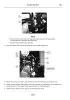
NOTE
•
Both inlet valves are installed the same way.
Driver side shown.
•
Install cable ties as required.
1.
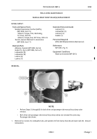
Install adapter (25) on inlet valve (21) with four screws (24).
2.
Install adapter (22) on inlet valve (21) with four screws (23).
-
-
-
-
-
-
-
-
-
-
-
-
-
-
-
-
-
-
-
-
-
-
-
-
-
-
-
-
-
-
-
-
-
-
-
-
-
-
Adhesives, solvents, and sealing compounds can burn easily, can give off harmful
vapors, and are harmful to skin and clothing.
To avoid injury or death, keep away
from open fire and use in well-ventilated area.
If adhesive, solvent, or sealing
compound gets on skin or clothing, wash immediately with soap and water.
3.
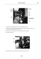
Apply sealing compound to threads of pipe (11) and elbow (2)
4.
Install pipe (11) on adapter (22) (WP 0318).
5.
Install elbow (2) on adapter (22) (WP 0318).
6.
Install electric motor and drive assembly (20) on valve (21) (WP 0248).
7.
Install pipe (11) on bracket (9) with cradle (19), U-bolt (18), and two locknuts (17).
Do not tighten locknuts.
HWT0092
WARNING
ICON 30, 44, 27
Back to Top


