TM-9-2320-361-20 - Page 1071 of 1207
TM 9-2320-361-20
Section IV. A-FRAME KIT MAINTENANCE
14-41. A-FRAME KIT REPLACEMENT
This task covers:
a. Removal
c. Installation
b. Inspection
INITIAL SETUP:
APPLICABLE MODELS
M35A2, M35A2C, M36A2
MATERIALS/PARTS
Lockwasher
Three locknuts
PERSONNEL REQUIRED
Two
REFERENCES (TM)
TM 9-2320-361-10
TM 9-2320-361-20P
EQUIPMENT CONDITION
Parking brake set (TM 9-2320-361-10).
Front lifting shackle removed, if required, w/winch
(para. 10-3) (task c. only).
Tailgate removed, if required, M35A2, M36A2
(para. 12-3), M35A2C (para. 12-4) (task c. only).
GENERAL SAFETY INSTRUCTIONS
Do not perform this procedure near high voltage
wires.
WARNIN G
Vehicle will become charged with electricity if A-frame contacts or
breaks high voltage line. Do not attempt to leave vehicle while high
voltage line is in contact with A-frame or vehicle. Leaving the
vehicle may result in injury to personnel.
1.
2.
3.
4.
5.
6.
7.
8.
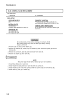
Remove adjusting screw (10) from bottom of each A-frame leg (9) and shackle bracket (11).
NOTE
Assistant will help with steps 2 through 4.
Push A-frame (12) towards cab (13).
Remove cable (4) from pintle hook (5) and lower A-frame (12) to ground.
Open snatch block (2) and remove winch cable (3).
Remove snatch block (2) from A-frame spreader tube (1).
Remove shackle pin (8), cable (4), and harness (7) from shackle (6).
Remove locknut (17), lockwasher (16), two washers (15), eyebolt plate (19), and eyebolt (14) from
rear cargo bed (18). Discard locknut (17) and lockwasher (16).
Remove two locknuts (27), nuts (20), washers (21), harness (7), two spacers (22), spreader tube (1),
and two studs (23) from leg extensions (24). Discard locknuts (27).
14-66
Back to Top


