TM-9-2320-361-20 - Page 177 of 1207
TM 9-2320-361-20
Table 2-4. Electrical Troubleshooting (Contd).
MALFUNCTION
TEST OR INSPECTION
CORRECTIVE ACTION
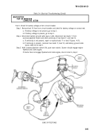
Test 3. Test input voltage to alternator.
Step 1. Turn headlights to OFF position. Stop engine.
Step 2. Disconnect lead 1 from lead 568 at alternator.
Step 3. Turn accessory/ignition switch to ON position.
Step 4. Check for battery voltage at contact end of lead 1. Voltage should be 24.0 Vdc.
a.
b.
c.
If voltage is not present, an open lead or bad connection exists in input circuit. Go to
test 6.
If voltage is 24.0 Vdc (normal), remove access cover on top of alternator to expose output
terminals.
Reconnect lead 1 to lead 568. Go to step 5.
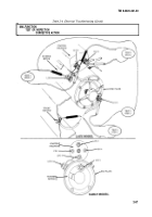
Step 5. Measure voltage at terminal end of lead 568.
a. If battery voltage is present (normal), the alternator is believed to be defective. Go to
test 4 and check positive output of alternator.
b. If voltage is not present, an open lead or bad contact exists in lead 568. Repair or replace
lead (para. 4-51), return to test 2.
Test 4. Test positive output of alternator.
NOTE
Access cover has been removed in test 3.
IA decrease in input voltage normally causes an increase in alter-
nator output voltage.
Step 1. Start engine (TM 9-2320-361-10).
Step 2. Set engine speed at 1200 rpm.
Step 3. Turn headlights and accessories to ON position.
Step 4. Use multimeter and measure alternator output voltage at positive terminal (lead 2).
a. If output voltage is between 24.0 and 26.0 Vdc, replace alternator (para. 4-3).
b. If output voltage is more than 28.5 Vdc, go to test 5 and check voltage drop on lead 2.
Test 5. Test voltage drop on lead 2.
Step 1. Place multimeter positive lead on alternator positive output. Place multimeter negative
lead on starter solenoid lug 2.
Step 2. If voltage drop on lead 2 is greater than 0.4 volts, replace or repair lead (para. 4-51). Go to
test 2.
Step 3. If voltage drop on lead 2 is less than 0.4 volts (normal), voltage regulator output is too high.
Replace alternator (para. 4-3).
Test 6. Test battery voltage into accessory/ignition switch (malfunction 2, test 4).
Step 1. Disconnect lead 1 from pin D of accessory/ignition switch.
Step 2. Turn accessory/ignition switch to ON position.
Step 3. Check voltage at pin D of accessory/ignition switch. Battery voltage should be present.
a. If battery voltage is present, go to step 4 and check continuity of lead 1.
b. If voltage is not present, perform malfunction 2, test 4, step 4, to test continuity of
accessory/ignition switch.
c. If continuity is present in accessory ignition switch, go to step 4.
2-92
Back to Top


