TM-9-2320-361-20 - Page 167 of 1207
TM 9-2320-361-20
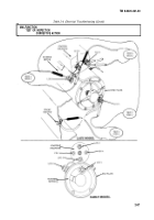
Table 2-4. Electrical Troubleshooting (Contd).
MALFUNCTION
TEST OR INSPECTION
CORRECTIVE ACTION
NOTE
M44A2 series vehicles may not be equipped with fuel pressure
switch. If vehicle is not equipped with fuel pressure switch, starter
switch output circuit would be wired directly to starter relay.
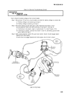
Test 3. Test for battery voltage on fuel pressure switch with accessory/ignition switch turned ON.
Step 1. Remove lead 74A from pin A of fuel pressure switch, push start button, and check for
battery voltage.
a. If voltage is not present, go to test 4.
b. If voltage is present, go to step 2.
Step 2. Disconnect battery ground cable (para. 4-48), remove lead 74B from pin B of fuel pressure
switch, and check continuity from lead 74B contact end to lug D on starter relay.
a. If no continuity is present, repair or replace lead 74B (para. 4-51).
b. If continuity is present, go to step 3.
Step 3. Check continuity of fuel pressure switch. With engine stopped, fuel pressure will be off and
contacts of switch will be closed. These normally closed contacts will be opened when
engine is running.
If no continuity is present between pins A and B, replace fuel presure switch (para. 4-37)
and go to test 1, Step 1.
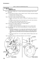
Test 4. Test for battery voltage into accessory/ignition switch pins A and C.
Step 1. Remove two leads 11 from accessory/ignition switch pins A and C. Using multimeter, check
for battery voltage on contact ends of leads 11.
a. If voltage is not present, go to test 5
b. If voltage is present, install both leads 11 into pins A and C and go to step 2.
Step 2. Observe voltmeter in dash for proper operation (TM 9-2320-361-10).
a. If voltmeter works, go to step 5.
b. If voltmeter does not work, go to step 3.
Step 3. Remove lead 27 from pin B of accessory/ignition switch. With accessory/ignition
turned ON, check for battery voltage at pin B.
a. If voltage is present, go to step 5.
b. If voltage is not present, go to step 4.
switch
Step 4. Remove leads 11 from pins A and C and lead 1 from pin D. With accessory/ignition switch
in ON position, check continuity between pins A and B followed by pins C and D.
a. If continuity is not found, replace accessory/ignition switch (para. 4-21). Check
continuity of new accessory/ignition switch before installation. Reinstall leads 11 in pins
A and C. Reinstall lead 27 in pin B and lead 1 in pin D. Attempt to start engine
(TM 9-2320-361-10).
b. If starter does not crank engine, go to step 5.
Step 5. Remove lead 74A from pin B of START switch. With accessory/ignition switch in ON
position, push start switch, and check for battery voltage at pin B.
a. If voltage is not present, go to step 6.
b. If voltage is present, perform continuity check on lead 74A.
c. If no continuity is present, replace or repair lead (para. 4-51).
2-82
Back to Top


