TM-9-2320-361-20 - Page 415 of 1207
TM 9-2320-361-20
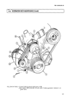
4-3. ALTERNATOR (60 AMPERE) AND MOUNTING BRACKET REPLACEMENT
This task covers:
a. Removal
c. Adjustment
b. Installation
INITIAL SETUP:
APPLICABLE MODELS
REFERENCES (TM)
All
TM 9-2320-361-10
MATERIALS/PARTS
TM 9-2320-361-20P
Two cotter pins
EQUIPMENT CONDITION
Eleven lockwashers
●
Parking brake set (TM 9-2320-361-10).
Adhesive sealant (Appendix C, Item 5)
●
Hood raised and secured (TM 9-2320-361-10).
Sealing compound (Appendix C, Item 23)
●
Battery ground cable disconnected (para. 4-48).
PERSONNEL REQUIRED
GENERAL SAFETY INSTRUCTIONS
Two
Alternator must be supported during removal and
installation.
CAUTION
Never operate the alternator with the output terminal
(POS)
disconnected. Damage to alternator will result.
NOTE
Tag wires for installation.
1.
2.
3.
4.
5.
6.
7.
8.
9.
4-4
Remove two screws (12) and lockwashers (11) from terminal cover (10). Discard lockwashers (11).
Pry cover (10) away from waterproofing sealant and remove cover (10),
Remove two screws (4), lockwashers (3), wire retaining strap (2), and spacer (1) from alter-
nator (25). Discard lockwashers (3).
Remove screw (6), lockwasher (5), and ground wire (7) from alternator (25). Discard lockwasher (5).
NOTE
●
Alternator has an AC terminal not used on M44A2 series trucks.
Ž Waterproofing sealant must be removed before removing wire in
step 5.
Remove nut (9), lockwasher (8), and wire (36) from stud (35). Discard lockwasher (8),
Disconnect wire (33) from wire (34).
Remove screw (18), lockwasher (19), and washer (17) from alternator adjusting arm (16) and
alternator (25). Discard lockwasher (19).
Remove nut (15), lockwasher (14), and alternator adjusting arm (16) from engine stud (13). Discard
lockwasher (14).
Remove two alternator belts (20) from alternator pulley (21).
Back to Top

