TM-9-2320-361-20 - Page 417 of 1207
TM 9-2320-361-20
4-3. ALTERNATOR (60 AMPERE) AND MOUNTING BRACKET REPLACEMENT (Contd)
1.
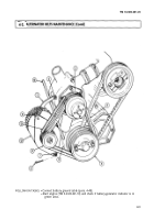
Install alternator pulley (21) (para. 4-4).
NOTE
Perform step 2 only if mounting bracket has been removed.
2. Install alternator mounting bracket (30) on engine (32) with three new lockwashers (29) and
screws (28). Tighten screws (28) 60-71 lb-ft (81-96 N•m).
3. Install alternator adjusting arm (16) to engine stud (13) with new lockwasher (14) and nut (15).
Finger tighten only.
WARNING
Alternator must be supported during installation. Failure to
support alternator may cause injury to personnel or damage to
equipment.
4. Install alternator (25) on mounting bracket (30) with two screws (27), four washers (26) and (24),
shims (31) as required, and two nuts (23). Finger tighten only.
5. Install alternator adjusting arm (16) on alternator (25) with washer (17), new lockwasher (19), and
screw (18). Finger tighten only.
6. Install and adjust alternator belts (20) (para. 4-2). Tighten two screws (27) 33-42 lb-ft (45-57 N•m).
7. Connect wire (33) to wire (34) and install two new cotter pins (22) through locknuts (23).
NOTE
●
Ensure terminals are clean before connections are made.
Ž Alternator has an AC terminal not used on M44A2 series trucks.
8. Install wire (36) on stud (35) with new lockwasher (8) and nut (9). Tighten nut (9) 45-55 lb-in.
(5-6 NŽm).
9. Install ground wire (7) to alternator (25) with new lockwasher (5) and screw (6). Tighten screw (6)
82-102 lb-in. (9-12 NŽm).
10. Install spacer (1) and wire retaining strap (2) over wires (7) and (36) on alternator (25) with two new
lockwashers (3) and screws (4). Tighten screws (4) 30-35 lb-in. (1-2 NŽm).
c. Adjustment
1.
2.
3.
4.
5.
6.
7.
8.
9.
10.
11.
4-6
Connect battery ground cable (para. 4-48) and start engine (TM 9-2320-361-10).
Set engine speed to 1200 rpm (TM 9-2320-361-10).
Turn on headlights (TM 9-2320-361-10) to place load on alternator.
Using multimeter, check alternator output voltage. Connect black lead to ground cable (7) and touch
red lead to wire (33). Output voltage should be 28.0 ± 0.2 VDC. If adjustment is required, continue
with next step. If no adjustment is required, go to step 7.
Remove pipe plug (37) from alternator (25).
Turn adjusting screw counterclockwise to increase or clockwise to decrease voltage.
Apply sealing compound to pipe plug (37) threads. Using hex head driver, install pipe plug (37) and
tighten 24-36 lb-in. (3-4 NŽm).
Turn off headlights (TM 9-2320-361-10).
Stop engine (TM 9-2320-361-10).
Seal wires (36), (7), and (34) and connectors and stud (35) completely with adhesive sealant.
Install terminal cover (10) on alternator (25) with two new lockwashers (11) and screws (12).
Back to Top


