TM-9-2320-361-20 - Page 425 of 1207
TM 9-2320-361-20
4-8. STARTER SWITCH REPLACEMENT
This task covers:
a. Removal
b. Installation
INITIAL SETUP:
APPLICABLE MODELS
All
REFERENCES (TM)
TM 9-2320-361-10
MATERIALS/PARTS
Lockwasher
TM 9-2320-361-20P
EQUIPMENT CONDITION
●
Parking brake set (TM 9-2320-361-10).
●
Battery ground cable disconnected (para. 4-48).
NOTE
Starter switch may be located to the right of the steering column on
older models.
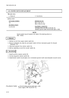
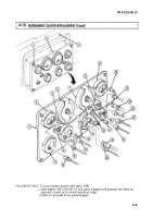
1. Remove nut (3) from engine starter switch (5).
2. Remove lockwasher (2), plate (l), and starter switch (5) from instrument panel (7). Discard
lockwasher (2).
3. Disconnect plug (6) from starter switch (5).
4. Remove adjusting nut (4) from starter switch (5).
b. Installation
1. Install nut (4) on starter switch (5).
2. Connect plug (6) to starter switch (5).
3. Install starter switch (5) and plate (1) on instrument panel (7) with new lockwasher (2) and nut (3).
FOLLOW-ON TASKS:
Connect battery ground cable (para. 4-48).
●
Start engine (TM 9-2320-361-10).
4-14
Back to Top


