TM-9-2320-361-20 - Page 427 of 1207
TM 9-2320-361-20
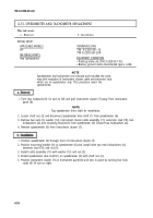
4-10. INSTRUMENT CLUSTER REPLACEMENT
This task covers:
a. Removal
c. Assembly
b. Disassembly
d. Installation
INITIAL SETUP:
APPLICABLE MODELS
All
MATERIALS/PARTS
Antiseize tape (Appendix C, Item 27)
REFERENCES (TM)
TM 9-2320-361-10
EQUIPMENT CONDITION
●
Parking brake set (TM 9-2320-361-10).
●
Battery ground cable disconnected (para. 4-48).
●
Air reservoirs drained (TM 9-2320-361-10).
GENERAL SAFETY INSTRUCTIONS
Do not disconnect air lines before draining air
reservoirs.
TM 9-2320-361-20P
a. Remova l
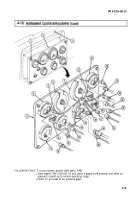
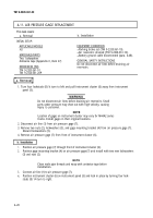
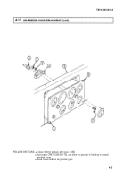
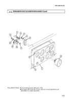
1. Turn four lockstuds (1) ¼ turn to left and pull instrument cluster (2) away from instrument
panel (3).
NOTE
Tag each wire, air tube, and drive shaft for installation.
Location of gages on instrument cluster may vary for M44A2
series trucks, Install gages in their original locations.
2.
3.
4.
5.
6.
7.
8.
9.
10.
11.
12.
Disconnect tachometer drive shaft (19) from tachometer (6).
Disconnect speedometer drive shafl (12) from speedometer (7).
WARNING
Do not disconnect air lines before draining air reservoir. Small
parts under pressure may shoot out with high velocity, causing
injury to personnel.
Disconnect air line (26) from air pressure gage (27).
Disconnect wire plug (16) from wire connector (17).
Disconnect wire plugs (5) and (25) from engine temperature gage (4).
Disconnect wire plugs (10) and (11) from oil pressure gage (9).
Disconnect wire plugs (20) and (18) from fuel gage (21).
Disconnect wire connector (14) from high beam indicator (15).
Disconnect wire connectors (13) and (23) from two indicator lamps (8).
Disconnect wire plug (22) from battery and generator gage (24).
Remove instrument cluster (2) from instrument panel (3).
4-16
Back to Top


