TM-9-2320-361-20 - Page 901 of 1207
12-72.
TM9-2320-361-20
This task covers:
a. 24-Volt Converter Receptacle RemovaI
c. 115-Volt Converter Receptacle Removal
b. 24-Volt Converter Receptacle Installation
d. 115-Volt Converter Receptacle Installation
INITIAL SETUP:
APPLICABLE MODELS
REFERENCES (TM)
M185A3, M109A3
TM 9-2320-361-20P
MATERIALS/PARTS
TM 9-237
Four screw-assembled lockwashers
EQUIPMENT CONDITION
Van body primary heater removed (para. 14-32).
NOTE
Tag all wires for installation.
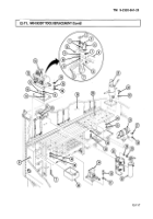
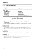
1. Remove socket (12) from receptacle (2).
2. Remove four screw-assembled Iockwashers (1) and receptacle (2) from van wall (6). Discard screw-
assembled lockwashers (1).
3. Pull back three insulation tubings (5) from three receptacle pins (3).
4. Unsolder and remove three wires (4) from three receptacle pins (3) (TM 9-237).
1. Insert three wires (4) into three receptacle pins (3) and solder in place (TM 9-237).
2. Install three insulation tubings (5) on three receptacle pins (3).
3. Install receptacle (2) on van wall (6) with four new screw-assembled lockwashers (1).
4. Install socket (12) on receptacle (2).
1. Remove plug (11) from receptacle (9).
2. Remove two screws (10) and receptacle (9) from van wall (6).
3. Remove two screws (7) and wires (8) from receptacle (9).
1. Install two wires (8) on receptacle (9) with two screws (7).
2. Install receptacle (9) on van wall (6) with two screws (10).
3. Install plug (11) on receptacle (9).
12-118
Back to Top


