TM-9-2320-361-34 - Page 377 of 764
TM 9-2320-361-34
15-16. VAN BODY CEILING PANEL REPLACEMENT
THIS TASK COVERS:
a. Removal
b.
Installation
INITIAL SETUP
APPLICABLE MODELS
M185A3
and M109A3
TOOLS
General mechanic’s tool kit
(Appendix B, Item 1)
PERSONNEL REQUIRED
Two
REFERENCES (TM)
TM 9-2320-361-20
TM 9-2320-361-34P
EQUIPMENT CONDITION
(Contd)
. Dome lights removed (TM 9-2320-361-20).
. Front and side window sashes removed (paras.
15-29 and 15-30).
●
Exhaust blower motor and bracket removed
(TM 9-2320-361-20).
●
Multibreaker and safety switch boxes removed
(paras. 15-26 and 15-27).
.115-volt receptacle strip removed (para. 15-21).
●
Primary or secondary van body heaters removed
(if installed) (TM 9-2320-361-20).
GENERAL SAFETY INSTRUCTIONS
EQUIPMENT CONDITION
Gloves, eyeshields, and dust mask must be worn
during panel removal and installation.
●
Parking brake set (TM 9-2320-361-10).
WARNING
Gloves, eyeshields, and dust mask must be worn during panel
removal and installation. Failure to do so may result in injury to
personnel.
NOTE
Ceiling panels on both sides of van ceiling are removed and installed
basically the same. This procedure covers one side.
a. Removal
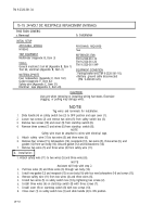
1. Remove twenty screws (5) and center ceiling panel (6) from two ceiling panels (1), ceiling panel (8), and
frame (2).
2. Remove thirty-two screws (7), two ceiling panels (1), and ceiling panel (8) from frame (2).
b.
Installation
1. Position two ceiling panels (1) and ceiling panel (8) on frame (2) and aline panel (1) screw holes (4)
with screw holes (3) in frame (2).
2. Install two ceiling panels (1) and ceiling panel (8) with thirty-two screws (7).
3. Install center ceiling panel (6) on frame (2), two ceiling panels (1), and ceiling panel (8) with twenty
screws (5).
15-66
Back to Top


